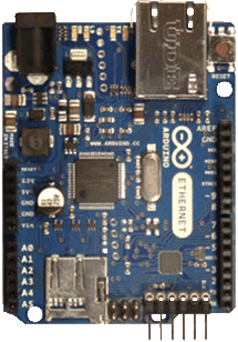
 Last year I worked on a little home project involving an Arduino Ethernet board. It all worked perfectly except that my program would hang after a few days operation. The time to failure wasn't consistent, sometimes it failed after only a couple of hours, often it took a week. But sooner or later it would stop sending data across the network and require a hard reset. Adding logging told me only that it was the network code that was stuck.
It turns out that this is a common problem with the Arduino Ethernet hardware. The fancy pants W5100 TCP/IP chip just goes on strike and needs to be reset. Using the Arduino's watchdog interrupt to software reset the CPU isn't enough, the W5100 needs to reset as well.
Reading the schematic provided a clue. The W5100's reset line is connected to the normal Arduino reset line (via a small reset controller IC), so resetting the Arduino by pulling the RESET line low resets the network chip as well.
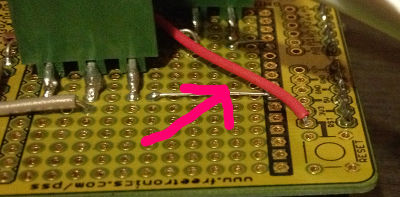
There is a right way to do this that involves a bunch of extra circuitry, and a wrong way that involves a piece of wire.
 Connecting the reset pin to one of the Arduino's digital IO pins is not recommended. The CPU requires that the reset line is help low for a certain amount of time to reset correctly and it can't hold the line low and reset simultaneously. That wouldn't make sense. Except that when I tried it the CPU reset every time and took the network chip with it. There is a capacitor between the RESET pin and GRD that I think helps out here, but my electronics is very weak.
I am still making use of the watchdog interrupt but instead of letting it reset the CPU, I handle the interrupt and bring the RESET line low using the digital IO pin.
#include <avr/wdt.h>

#define RESET_IO_PIN 3

void setup()
{
    //  Some people recommend setting the IO pin to HIGH on start up
    //  but it is better to leave it floating as INPUT. Pulling it HIGH interferes
    //  with the normal reset mechanism, and the pin is held HIGH by a pull-up
    //  resister anyway
    //  digitalWrite( RESET_IO_PIN, HIGH );
    //  pinMode( RESET_IO_PIN, OUTPUT );

    noInterrupts();
    wdt_reset();
    // these cryptic lines set the watchdog timer control register
    // to trigger an interrupt (not reset) after 8 seconds. The normal
    // Arduino function assumes you want to reset, so we can't use it here.
    // See the ATmega328P Datasheet section 10.9.2 for the gory details
    MCUSR &= ~(1<<WDRF);
    WDTCSR |= (1<<WDCE) | (1<<WDE);
    WDTCSR = (1<<WDP0) | (1<<WDP3) | (1<<WDIE); /* 8.0 seconds */
    interrupts();
}

ISR(WDT_vect)
{
    // The watchdog timer has fired, pull the pin low
    digitalWrite( RESET_IO_PIN, LOW );
    pinMode( RESET_IO_PIN, OUTPUT );
}

void loop()
{
    wdt_reset();
    // do some stuff here, if you don't call wdt_reset() more frequently
    // than 8 seconds the Arduino will reset
}
I spent weeks trying to figure out what was going on, hopefully this post will help somebody in the same situation.