Last week I wrote about starting with digital electronics with the Arduino prototyping platform . Getting something working was easy enough but I was dissatisfied with ugly result, especially when my friend Lloyd showed up with his extremely tidy version of the same idea. The piece of cardboard had to go!
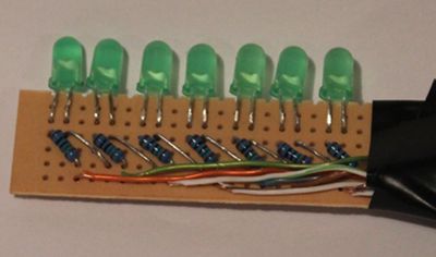
Front 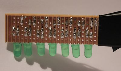
Back My first version used a breadboard and uncut LED leads because I thought that I would want to dismantle the components for reuse. However I have since realised that I am a grown man with a career and can easily afford the $4.50 material cost. Behold POV version 2:
I won't be entering this in any soldering competitions but it works OK.
The code has also changed. Compiling in what amounts to a 2D bitmap was a quick way to get something up and running but it wasn't very flexible, especially since in the future I want to display long strings of text. This means storing glyphs (letter shapes) for every letter of the alphabet (plus digits and symbols) - what I needed was a proper font; what I got was this:

I then turned to Python to generate the program data to embed in the new Arduino code. This script slices the image vertically, generating one byte (actually only 7 bits) for each slice of pixels. What comes out is a long list of byte values that can be output directly to the Arduino's IO pins to display each section of the text, along with a set of indexes that map letters to the start and end positions of individual glyphs in the array.
import sys

def GetSlice(i, pos):
    t = 0
    for q in range( pos, len(i), len(i) / 7 ):
        t = t * 2
        if ( i[q] != '\x00' ):
            t = t + 1
    return t

def GetGlyph( i, pos ):
    end = pos
    start = pos
    data = []
    while (end < len(i) ):
        t = GetSlice( i, end )
        if ( t == 0 ):
            break;
        data.append( t )
        end = end + 1
    return (start, end, data)

def GetFont( d ):
    result = []
    i = 0
    currentIndex = 0
    indices = []
    while ( i < len(d) / 7 ):
    (start, end, data) = GetGlyph( d, i )
    if ( len(data) == 0 ):
        break
    i = end + 1
    indices.append( currentIndex )
    currentIndex = currentIndex + len(data)
    result.extend( data )
    return ( result, indices )

if __name__ == '__main__':
    if ( len(sys.argv ) != 3 ):
        print "USAGE: program <input> <output>"
        exit()
    data = []
    i = file( sys.argv[1], "rb" )
    data = i.read()
    i.close()
    ( d, indices ) = GetFont( data )
    o = file( sys.argv[2], "w" )
    o.write( "static const int indices[] = { " + ",".join(map(str, indices ) ) + " }; ")
    o.write("\n")
    o.write( "static const unsigned char fontdata[] = { " + ",".join(map(str, d)) + "};")
    o.write("\n")
    o.close()
This scheme is more complex that the original bitmap but allows arbitrary text to be display without lots of editing. The modified Arduino code now looks like this. The first two lines contain the new font data, and you can see that the text to display is simply declared on line 5.
static const int indices[] = { 0,4,8,12,16,19,22,26,30,33,37,42,45,52,59,63,67,71,75,79,82,86,91,96,101,106,111,116,121,126,131,136,141,146,151,156,161,163,165,167 };
static const unsigned char fontdata[] = { 63,72,72,63,127,73,73,54,62,65,65,34,127,65,65,62,127,73,65,127,72,64,62,65,69,39,127,8,8,127,65,127,65,2,1,1,126,127,8,20,34,65,127,1,1,63,64,64,60,64,64,63,127,32,16,8,4,2,127,127,65,65,127,127,72,72,48,62,65,71,62,127,72,76,51,50,73,73,38,64,127,64,126,1,1,126,112,12,3,12,112,126,1,15,1,126,65,54,8,54,65,96,16,15,16,96,67,69,73,81,97,62,69,73,81,62,17,33,127,1,1,71,73,73,73,49,65,65,73,73,54,24,40,72,127,8,121,73,73,73,6,62,73,73,73,6,65,66,68,72,112,54,73,73,73,54,48,73,73,73,62,3,3,123,123,27,27,127};

static int outputPins[] = { 12, 11, 10, 9, 8, 7, 6 };
static char text[] = "ANDREW";

void setup()
{
  for (int i = 6; i<=12; ++i)
  {
    pinMode(i, OUTPUT);
    digitalWrite(i, HIGH);
  }
  pinMode(13, OUTPUT);
  digitalWrite(13, LOW);
  delay(2000);
}

void loop()
{
  byte row = 0;
  byte endRow = 0;
  char* currentChar = text;

  while (1)
  {
    if (*currentChar == 0)
      currentChar = text;
    if ( row == endRow )
    {
        char t = *currentChar;
        currentChar++;
        t = t - 'A';
        row = indices[t];
        endRow = indices[t+1];
    }
    while (row != endRow)
    {
      byte mask = 64;
      for (byte pin = 0; pin < (sizeof( outputPins) / sizeof(outputPins[0])); ++pin )
      {
        digitalWrite( outputPins[pin], (fontdata[row]&mask)? HIGH : LOW  );
        mask = mask / 2; // divide mask by two, moving it down one bit
      }
      row++;
      delay(1);
    }
    for (byte pin = 0; pin < (sizeof( outputPins) / sizeof(outputPins[0])); ++pin )
    {
      digitalWrite( outputPins[pin], LOW);
    }

    delay(1);
  }
}
Still to do: This code is not very efficient. It uses digitalWrite() in a loop to turn on the LEDs. digitalWrite() is very easy to use but if you look at the source code you will see it does all sorts of unnecessary stuff for this job. I plan to replace it with direct writes to the required Arduino IO registers.
I also want to make the whole thing interrupt driven to free up the CPU. Why would I want the extra CPU time? I have plans for that as well...